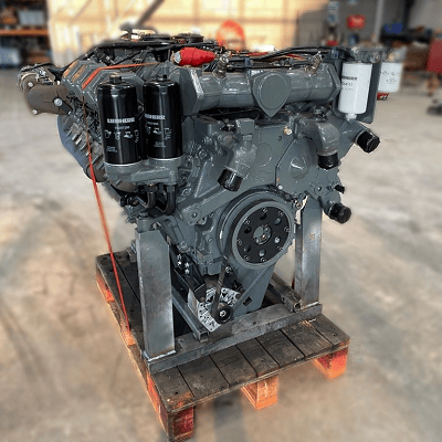
The process of a dyno test on a Liebherr engine

When it comes to heavy machinery, reliability and power are paramount. Liebherr, a name synonymous with innovation and excellence in engineering, stands tall as a pioneer in the realm of heavy equipment and machinery. From towering cranes to robust excavators, Liebherr’s engineering prowess extends to the heart of these machines. We delve into the world of dyno testing a Liebherr engine, uncovering the meticulous process behind unleashing the raw power concealed within.
The foundation of excellence
Before we embark on the journey of dyno testing, it’s crucial to understand the foundation upon which Liebherr engines are built. With decades of engineering expertise and commitment to quality, Liebherr engines are crafted to withstand the most demanding environment and deliver unparalleled performance. Each component is meticulously designed and rigorously tested to ensure reliability, efficiency and longevity.
The process
1 Preparation: The engine undergoes meticulous preparation before being mounted onto the dynamo meter. This includes ensuring all connections are secure, fluids are filled to the appropriate levels, and sensors are properly calibrated.
2 Mounting: The engine is carefully mounted onto the dynamometer, a specialized device designed to simulate real-world operating conditions. Precision is paramount during this step to ensure accurate results.
3 Initial checks: Once mounted, a series of initial checks are conducted to verify proper alignment, connection integrity, and functionality of all engine systems.
4 Warm-up: The engine is started and allowed to warm up to operating temperature. This ensures consistent results and minimizes the risk of damage during testing.
5 Baseline testing: With the engine warmed up , baseline tests are conducted to establish initial performance metrics. This includes measuring power output, torque, fuel consumption, and emissions at various RPM levels.
6 Load testing: The engine is subjected to progressively increasing loads to simulate different operating conditions, such as idle, partial load and full load. This allows engineers to assess performance across the entire operating range and identify any potential issues or optimization.
7 Data analysis: Throughout the testing process, data is continuously collected and analyzed in real-time. Advanced instrumentation and software are used to monitor performance metrics and identify trends or anomalies.
8 Optimazation: Based on the data analysis, adjustments may be made to optimize engine performance. This could involve fine-tuning fuel injection timing, adjusting air-fuel ratios, or optimize turbocharger boost pressure.
9 Validation: Once testing is complete, the results are meticulously reviewed and validated against predetermined criteria and specifications. Any deviations or anomalies are thoroughly investigated to ensure accuracy and reliability.
10 Reporting: Finally, a comprehensive report is generated detailing the results of the dyno testing, including performance metrics, observations, and any recommendations for further optimization or refinement.
The outcome of dyno testing
Dyno testing a Liebherr engine is more than just a routine procedure – it’s a testament to the unwavering commitment to excellence that defines Liebherr’s engineering philosophy. By subjecting their engines to rigorous testing and analysis, Liebherr ensures that each engine delivers the uncompromising performance, reliability, and efficiency that customers expect.
In conclusion, dyno testing a Liebherr engine is not just about measuring power output. It’s about unlocking the true potential of these remarkable engines and ensuring they exceed expectations in the most challenging environments imaginable.
Feiyiya Inclined Plate Clarifiers Use Gravity & Innovative Engineering
A gravity clarifier is the most economical method of removing solids from liquids, using natural gravity as the source of energy and it is free. A clarifier simply provides a non-turbulent zone where heavier than liquid solids, suspended by turbulence, are given sufficient time to settle to a quiescent surface. The HEI inclined plate clarifiers are compact units with multiple layers of settling area utilizing less than 25% of the floor space required by conventional clarifiers.
Principle of Clarifiers
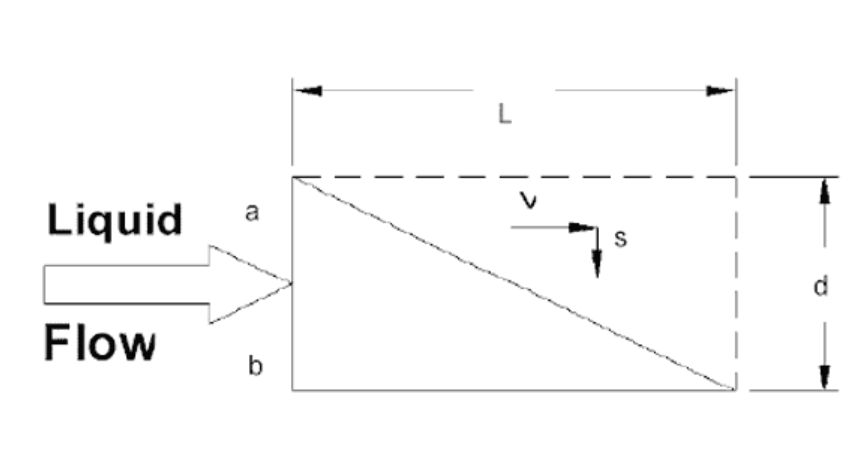
A particle carried forward by the velocity of the liquid flow must settle at a rate that allows it to reach the bottom before passing through the clarifer. Thus, particles beginning at a point [a" must traverse some route lying between ab and ab` in order to avoid being carried over the outlet.

If V is the horizontal velocity of the liquid, S the solids particle vertical settling velocity, L the length of the settling device, and D its depth, then particles entering at point A will settle to the bottom of the device only if V does not exceed: S(L/D)Since Vmax / S = L / D then, Vmax = S (L / D)
Therefore, the velocity at which a horizontal clarifying device may be operated successfully is directly proportional to its length and inversely proportional to its depth.
This analysis applies to multiple horizontal plate units also. The spacing between plates is usually a few inches as opposed to a depth of several feet in a horizontal tank; therefore, [settling-out" times are dramatically reduced. The flow must be non-turbulent to prevent settled solids from being re-entrained within the moving liquid. Small plate spacing and a large surface area permits laminar flow at higher velocities than large horizontal tanks would allow.
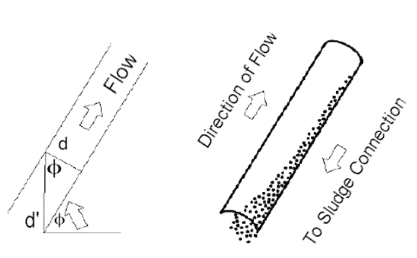
Horizontal clarifying devices become self-flushing if they are inclined at an angle which exceeds the angle of repose of the settled solids. In such cases, flow enters the lower end of the device where settling particles move to the floor eventually sliding back out the entrance. Clear effluent leaves the top of the device.
 However, when the device is inclined, the furthest settling particles no longer fall through distance D but some longer distance D`. This new longer settling distance D` is related to D by the relation: D = D` cos Ø.
Theta [Ø" is the angle, the device is inclined to the horizontal plane. Thus settling distance is increased by the factor: 1/cos Ø In the case where Ø = 60º, 1/cos Ø = 2.
The maximum settling distance is twice the distance between the plates. It is apparent then that the lower the angle of inclination, the smaller the settling distance. However, the angle of inclination must exceed the angle of repose of the solids to be separated. The previous equation may be modified to express the cosine of an inclined plate clarifying system as:
Vmax = L / (D / cosØ) (s) = L·cosØ / D (s)
Inclined Plate Clarifiers
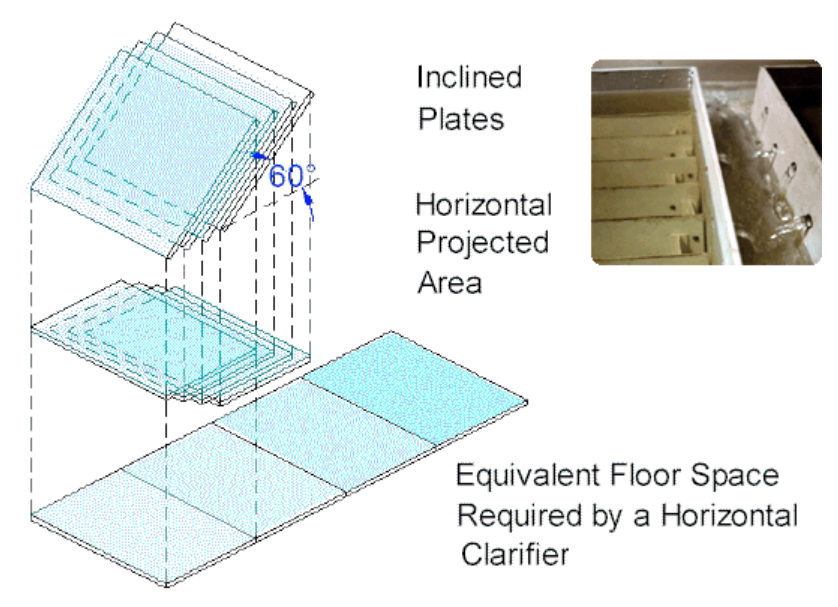
A reduction of the required floor space is acquired by diminishing the separation between the horizontal plates to a few inches and stacking the settling surfaces. Inclining the plates to provide self flushing, 45º for heavy particles and 60º for light particles, reduces the available horizontal projected area (effective settling area) by a factor equivalent to the cosine of the angle. The surface area diagram (below) graphically compares the floor space requirements of an HEI inclined plate clarifier with the equivalent horizontal projected settling area.
Settling Rate
The settling rate for a specific solids should be determined by standard laboratory tests. Light particles, such as metal hydroxides, usually require a design parameter of 0.25 – 0.50 gallons per minute per square foot of horizontal projected area. These low density solids require the inclined plates to be set at a 60º angle to induce the particles to slide down the plate. Heavier particles (such as sand that easily flow) will readily slide from plates set at a 45º angle.

Maximum flow rate of an inclined plate clarifier is based on the flow rate per unit of a horizontally projected surface area. Retention time in the clarifier is not a design criteria. However, attaining optimum performance requires the prudent design to recognize several additional, very important factors.
Inclined plate clarifier, Lanmei inclined plate clarifier, Inclined Tube Settler,High-Efficiency Inclined Tube
Wuxi Feiyiya Environmental Protection Technology Co., Ltd. , https://www.feiyya.com
![<?echo $_SERVER['SERVER_NAME'];?>](/template/twentyseventeen/skin/images/header.jpg)