Relative sliding coefficient gear transmission, the two gears have relative sliding in the tangential direction, which is the root cause of gear wear, the relative sliding of the gears 3 other matters needing attention 1) control the basic size of the prefabricated holes, requirements and size of the front guide Equal, the tolerance band takes e8, and the perpendicularity between the center line of the pre-made hole and the reference end surface of the workpiece is within 0.04mm/100mm.
2) After the broach wears, it should be sharpened in time. In order to avoid excessive damage and chipping of the broach, the number of teeth working at the same time cannot exceed 6 teeth. 3) Cooling should be sufficient. When processing the inner hole of steel, 10 emulsion can be used, and the cooling method is used before and after cooling. The coolant supply is not less than 10L/min. The front coolant acts as lubrication and cooling, and the latter coolant cools the broach and washes off the chips. The role.
The derivation of the calculation formula of the normal line wear amount According to the elastic alternative theory, the mechanical model of the two-gear meshing can be regarded as the contact of two cylinders, and the radius of the cylinder is 1 and 2, respectively. After the application of the pressure Fnk, the contact surface is elastically deformed to form a rectangular contact surface having a width of 2a.
Therefore, in a certain rotation time t, the total friction distance is: L1=S1n1t(11)L2=S2n2t(12) The normal line wear amounts of the two gears are: h1=In1L1=In1S1n1th2=In2S2n2t , n1, n2 respectively indicate the rotation speed of the pinion and the large gear; In1 and In2 respectively show the wear characteristic coefficients of the pinion and the large gear, which are related to factors such as gear material, tooth surface hardness and environmental conditions, and are determined by experiments. Combine the equations (2), (8), (9), (10), (11), and (12) to obtain h=h1 h2=4FnkB121 2(1-21E1 1-2E2)(In11n1t In22n2t)(13) By substituting the parameters 1, 2, 1, 2, and Fnk of point K into (13), the maximum normal line wear amount of point K can be calculated.
Allowing the determination of the wire wear amount [h] As described above, the most direct result of the tooth wear is to make the tooth thickness thin. Assume a pair of gear drives. When the pinion gear teeth are thinned by E1, it is obvious that the large gear wheel will be rotated clockwise by a certain angle 1 regardless of the original rotation speed n2, so that the large gear gear is decelerated on the basis of the original n2. When the large gear teeth are thinned by E2, the large gears will also rotate a certain angle 2 in the clockwise direction, which in turn causes the large gears to decelerate. It can be seen that the tooth thickness of the two gears is thinned, resulting in the operation of the large gears. Consistently, the angle of rotation of the large gear in the clockwise direction is =1, and the geometric relationship is known: =Erb2=E1 E2rb2=h1 h2rb2=hb2 (14) where E1 and E2 are the tooth thicknesses of the two gears in the normal direction. The thinning type (14) shows the transmission error of the large gear due to the wear of the gear teeth. If the accuracy of the gear transmission is controlled, the allowable wear amount of the gear teeth can be obtained by (14) [h]=rb2(15) 4 wear life calculation formula synthesis (1), (13), (15) can get the gear wear wear life ttrb24FnkB121 2 (1-21E1 1-2E2) (In1n11 In2n22) (16), the meaning of the symbol and the same value before.
Conclusion (1) The calculation formula of the normal line wear amount derived from this paper is suitable for any meshing point. When calculating, the relevant parameters of the meshing point can be substituted. At the same time, the formula is also suitable for gears that are not involute profiles. (2) Gear wear is a very important factor leading to gear transmission error. The formula derived in this paper is especially suitable for gear transmission with light load and high transmission accuracy requirements.
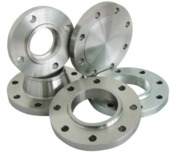
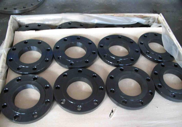
Flange mainly used for connecting two pipes, used at pipe end; also connection between the two devices. Steel flange materials can be divided into: low carbon steel flanges, mid-carbon steel flanges , high carbon steel flanges, alloy steel flanges. Steel flange has a high strength,good toughness,and high resistance to corrosion,high pressure and temperature, more excellent sealing performance, a wide usage range. Steel flange is widely used in petroleum, chemical, food, dairy, pharmaceutical, machinery manufacturing, sewage treatment, municipal water supply pipelines, military and medical industries
Flange containing integral flange (IF), threaded flange (Th), plate flange (PL), weld neck flange (WN), slip on flange (SO), socket weld flange (SW), loose flange (PJ / SE), flat welding ring loose flange (PJ / RJ), Blind Flange (BL)
Product Steel Flange
Size:DN10-DN2500
Materials: 20#.A105.Q235A.12Cr1MoV.16MnR.15CrMo.18-8.321.304.304L.316.316L
Pressure: Pn2.5-Pn320,Class150-Class2500,5K-30K
Standard:ANSI,JIS,DIN,GOST.......
Crafts: Forging
Connection: Welding,Bolt.
Package: Wooden boxes,Wooden pallets,According to customer requirements.
Brand Name: HY
Place of Origin: China (Mainland)
Certification: ISO.UKS.SGS.BV
Application: Chemical, Water, Oil and gas, Electricity


Steel Flange,Carbon Steel Flange,Standard Steel Flange,Stainless Steel Endplate Flange
CANGZHOU HAOYUAN PIPE FITTINGS MFG CO.,LTD , https://www.pipefitting-china.com
![<?echo $_SERVER['SERVER_NAME'];?>](/template/twentyseventeen/skin/images/header.jpg)