1. Control system simulation composition The main simulation object of the power station training simulator is the large-capacity unit set, including the process simulation and the control system simulation. The simulation of power plant automation control system generally includes: CCS, BMS or FSSS, steam turbine digital electrohydraulic control system (DEH), feed water pump micro-electro-hydraulic control system (MEH), Steam Turbine Bypass Control System (BPC) and Auxiliary Machine Sequence Control System (SCS).
Supporting software for the development of power plant training simulators include ROSE system of CAE Electronics Canada, CET-RAN system of ABB USA, STAR-90 system of Simulation and Control Company of North China Electric Power University, ASCA system of Asian Simulation Control Company, and Tsinghua University. Energy simulation company's ISSE system. No matter what kind of simulation supports the software, some control algorithms and logic in the control system are more complicated and the number of variables is large, but the basic principle is the same. The establishment of the mathematical model of the control system is mainly based on the adjustment system diagram and logic diagram of each system, and the corresponding algorithm is selected according to its function. The 300MW simulator of Baoji No.2 Power Generation Company adopts STAR-90 simulation support software developed by the control company of North China Electric Power University.
2. Characteristics of STAR-90 Simulation Support Software and Main Algorithms of Control System STAR-90 simulation support system has the following features: (1) Engineering modeling;
(2) Provide online interactive modeling modification methods;
(3) The model database is automatically generated in the modeling;
(4) Support multi-model operating environment;
(5) Each module can select the corresponding calculation step according to the need;
(6) All support system software (except for the algorithm subroutines written in FORTRAN language) is written in C language, and has strong portability;
(7) The algorithm library is rich in content, and can basically cover the simulation needs of various types of thermal power plants. The process algorithm is established based on the physical mechanism and has high simulation accuracy.
(8) The engineer desk/coacher desk interface was developed using the X-Windows programming environment, with multi-window function, beautiful display screen and friendly interface;
(9) Automatically generate AUTOCAD-style module configuration diagram.
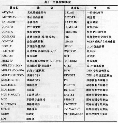
The single-capacity 300 MW unit of Baoji Second Generation Power Co., Ltd. adopts the Westinghouse WDPF distributed control system. The main control algorithms adopted for this distribution system are shown in Table 1. Some of them are conventional algorithms, and some of them are dedicated algorithms based on WDPF system diagrams and logic diagrams.
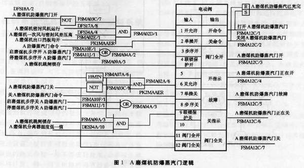 3 control system modeling configuration In the power plant distributed control system, all thermal signals and parameters can be divided into 2 categories, namely, switch and analog. The switch control is only a simple logic control and does not participate in direct adjustment. The entire system has only two states "1" and "0." Through logic algorithms such as AND, OR, NOT, TRIGGER, etc., the simulation of program control and interlock protection system can be fully realized. Both BMS and SCS are pure logic controls. Figure 1 shows the coal mine explosion-proof steam gate logic for FSSS system A. Figure 2 shows the model configuration implemented in simulation language. It can be seen that the logical configuration is relatively easy, but the entire control system has many logical configuration variables and the workload is large. Different power station logic and protection systems are different, but it is very easy to implement logic relationships in various high-level languages.
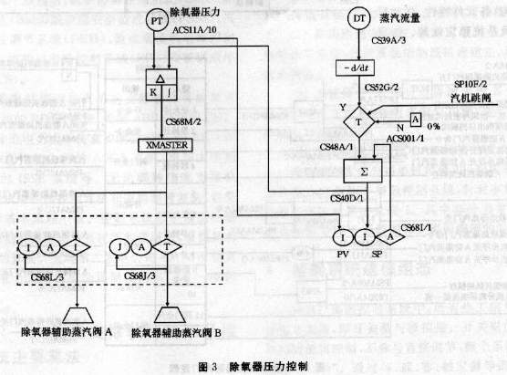
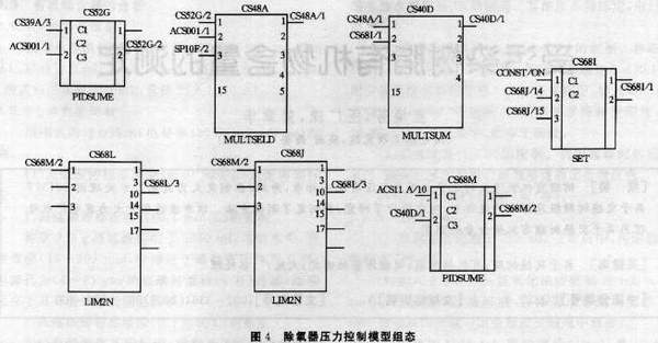
CCS, DEH, MEH, and BPC have both adjustment functions and logic control functions. Regardless of the structure of the control system and how the control instrument changes, the sub-loops of the control system are mostly dominated by single-loop, cascade, and feed-forward control methods that consist of traditional PID algorithms. The configuration of the control loop is mainly composed of a regulator algorithm, an operator algorithm, a setpoint algorithm, and the like. Figure 3 shows the adjustment of the deaerator pressure control system. Figure 4 shows the simulation model configuration.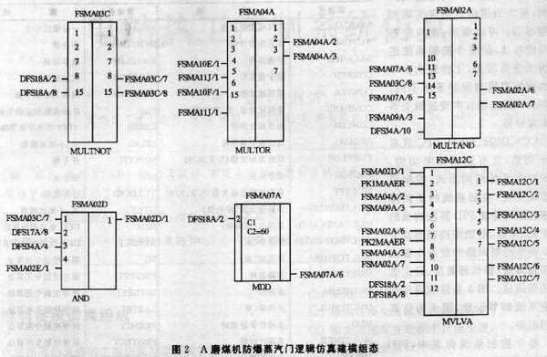
 In the entire control system simulation, the setting of the PID regulator parameters is very important. The quality of single-loop feedback control system depends on the structure of the system, the characteristics of each component, the form and amplitude of the disturbance, and the stability of the system. The simulator thermodynamic control adjustment objects are simulation processes and equipment models, such as drum level, main steam temperature, etc. These parameters are calculated by process and equipment model algorithms. The characteristics, simulation level, and accuracy of the algorithm will directly affect the quality of the regulation system. . In the normal condition of each device and component, whether or not the system can maintain the best working condition depends on the adjustment parameters. In the simulator, the setting of PID parameters generally adopts the engineering setting method (experience trial and error). The 300 MW turbine simulator control system of Baoji No.2 Power Generation Company has high simulation accuracy, and the automatic and protective investment rate is 100%.
4 control system simulation and actual distributed control system to achieve the different actual control system configuration through the control system software ladder diagram, configuration diagram form, control software, including the corresponding text algorithm, adjustment algorithm, logic algorithm, etc., can achieve control All system adjustments and logic controls. The control configuration is graphical, and analysis, configuration and maintenance are more intuitive and convenient. In the actual system, the control system accepts actual measurement signals from the site, such as differential pressure, pressure, and temperature. In order to ensure the measurement accuracy, in many cases, the software needs to complete the signal processing and compensation. For example, the water level of the drum needs to be compensated by the pressure and temperature signals. The steam flow signal also needs to be calculated from the differential pressure, pressure, and temperature signals. In the simulation system, the thermal process and equipment undergo many ideal assumptions. The thermal parameters calculated by the process and equipment algorithms generally do not need to be processed. If necessary, only signal nominal calculations are performed. The regulator parameters of the same control loop cannot be exactly the same because the emulation object and the actual device in the emulation machine are not identical, and the setting of the PID parameter is also inconsistent with the site. In order to realize some special functions of the field control system, some corresponding algorithms need to be added in the simulation system.
5 Simulation of control system The simulation of the thermal control system of the power plant has achieved a 1:1 simulation of the simulator and the site. The system can fully and systematically train the operation personnel of the unit to improve the monitoring capability and operation technology.
The application simulator can optimize the controller parameters so that each control system is always in the best state of regulation quality. After the control system is modified, the simulation engineer can make a dynamic response after the control system data changes on the simulator. When it is found that the regulation does not meet the regulation, the problems in the engineering data can be immediately identified and modified in time. To improve the regulation quality, some conventional regulators can be changed to variable parameter regulators.
With STAR-90 simulation software, the control system has complete functions and high simulation accuracy. If the modeling configuration can be implemented by icons, it will be more intuitive and convenient for users, and it is also easy to maintain and analyze. In addition, the modeling process data has huge variables and the workload is large. If it can be effectively combined with the field control system software, the workload will be greatly reduced, and it is also more conducive to the operation and training and the development of large-scale unit distributed control system simulation software. .
Supporting software for the development of power plant training simulators include ROSE system of CAE Electronics Canada, CET-RAN system of ABB USA, STAR-90 system of Simulation and Control Company of North China Electric Power University, ASCA system of Asian Simulation Control Company, and Tsinghua University. Energy simulation company's ISSE system. No matter what kind of simulation supports the software, some control algorithms and logic in the control system are more complicated and the number of variables is large, but the basic principle is the same. The establishment of the mathematical model of the control system is mainly based on the adjustment system diagram and logic diagram of each system, and the corresponding algorithm is selected according to its function. The 300MW simulator of Baoji No.2 Power Generation Company adopts STAR-90 simulation support software developed by the control company of North China Electric Power University.
2. Characteristics of STAR-90 Simulation Support Software and Main Algorithms of Control System STAR-90 simulation support system has the following features: (1) Engineering modeling;
(2) Provide online interactive modeling modification methods;
(3) The model database is automatically generated in the modeling;
(4) Support multi-model operating environment;
(5) Each module can select the corresponding calculation step according to the need;
(6) All support system software (except for the algorithm subroutines written in FORTRAN language) is written in C language, and has strong portability;
(7) The algorithm library is rich in content, and can basically cover the simulation needs of various types of thermal power plants. The process algorithm is established based on the physical mechanism and has high simulation accuracy.
(8) The engineer desk/coacher desk interface was developed using the X-Windows programming environment, with multi-window function, beautiful display screen and friendly interface;
(9) Automatically generate AUTOCAD-style module configuration diagram.
The single-capacity 300 MW unit of Baoji Second Generation Power Co., Ltd. adopts the Westinghouse WDPF distributed control system. The main control algorithms adopted for this distribution system are shown in Table 1. Some of them are conventional algorithms, and some of them are dedicated algorithms based on WDPF system diagrams and logic diagrams.


CCS, DEH, MEH, and BPC have both adjustment functions and logic control functions. Regardless of the structure of the control system and how the control instrument changes, the sub-loops of the control system are mostly dominated by single-loop, cascade, and feed-forward control methods that consist of traditional PID algorithms. The configuration of the control loop is mainly composed of a regulator algorithm, an operator algorithm, a setpoint algorithm, and the like. Figure 3 shows the adjustment of the deaerator pressure control system. Figure 4 shows the simulation model configuration.


4 control system simulation and actual distributed control system to achieve the different actual control system configuration through the control system software ladder diagram, configuration diagram form, control software, including the corresponding text algorithm, adjustment algorithm, logic algorithm, etc., can achieve control All system adjustments and logic controls. The control configuration is graphical, and analysis, configuration and maintenance are more intuitive and convenient. In the actual system, the control system accepts actual measurement signals from the site, such as differential pressure, pressure, and temperature. In order to ensure the measurement accuracy, in many cases, the software needs to complete the signal processing and compensation. For example, the water level of the drum needs to be compensated by the pressure and temperature signals. The steam flow signal also needs to be calculated from the differential pressure, pressure, and temperature signals. In the simulation system, the thermal process and equipment undergo many ideal assumptions. The thermal parameters calculated by the process and equipment algorithms generally do not need to be processed. If necessary, only signal nominal calculations are performed. The regulator parameters of the same control loop cannot be exactly the same because the emulation object and the actual device in the emulation machine are not identical, and the setting of the PID parameter is also inconsistent with the site. In order to realize some special functions of the field control system, some corresponding algorithms need to be added in the simulation system.
5 Simulation of control system The simulation of the thermal control system of the power plant has achieved a 1:1 simulation of the simulator and the site. The system can fully and systematically train the operation personnel of the unit to improve the monitoring capability and operation technology.
The application simulator can optimize the controller parameters so that each control system is always in the best state of regulation quality. After the control system is modified, the simulation engineer can make a dynamic response after the control system data changes on the simulator. When it is found that the regulation does not meet the regulation, the problems in the engineering data can be immediately identified and modified in time. To improve the regulation quality, some conventional regulators can be changed to variable parameter regulators.
With STAR-90 simulation software, the control system has complete functions and high simulation accuracy. If the modeling configuration can be implemented by icons, it will be more intuitive and convenient for users, and it is also easy to maintain and analyze. In addition, the modeling process data has huge variables and the workload is large. If it can be effectively combined with the field control system software, the workload will be greatly reduced, and it is also more conducive to the operation and training and the development of large-scale unit distributed control system simulation software. .
Pe Label,Transparent Pe Sticker,White Pe Sticker,Pe Film Label
SOONTOMAX (TAISHAN) LABEL MATERIAL CO.LTD , https://www.stmlabel.com
![<?echo $_SERVER['SERVER_NAME'];?>](/template/twentyseventeen/skin/images/header.jpg)