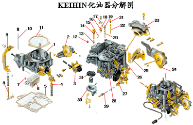
Carburetor exploded view

1. Carburettor body 2, choke valve vacuum controller 3, electromagnetic idle shut-off valve 4, vacuum control enriched plunger 5, gasket 6, float 7, inlet needle valve 8, acceleration pump transmission rod 9, acceleration The pump lever 10, the accelerating pump push rod 11, the gasket 12, the idle air volume hole 13, the main chamber idle volume hole 14, the screw plug 15, the main cavity main volume hole 16, the enrichment valve 17, the baffle plate 18, and the sub cavity Main orifice 19, main chamber air compensation orifice 20, main cavity emulsified foam tube 21, sub-cavity air correction orifice 22, secondary cavity emulsification foam tube 23, sub-cavity vacuum controller 24, air-conditioning vacuum controller 25, manipulation pull Cable bracket 26, carburetor lower body 27, throttle manipulation rocker arm 28, idle adjustment screw 29, carbon monoxide adjustment screw 30, accelerating pump cover 31, accelerating pump film
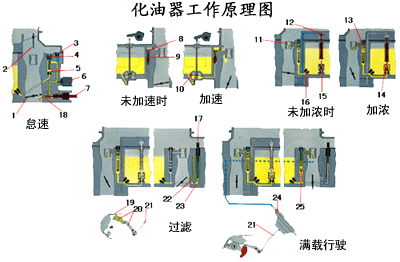
Carburetor working principle diagram

1. Throttle valve 2, choke valve 3, idle air volume hole 4, screw plug 5, main chamber idle volume hole 6, electromagnetic idle stop valve 7, carbon monoxide adjustment screw 8, acceleration pump nozzle 9, acceleration pump needle valve 10, Acceleration pump 11, main chamber small throat 12, enriched plunger 13, main chamber dairy cowlized foam tube 14, push rod 15, thickened valve orifice 16, main chamber main orifice 17, sub chamber transitional foam tube 18, Idling nozzle 19, throttle cable 20, sub-cavity transition nozzle 21, connecting rod 22, sub-cavity transition nozzle 23, sub-cavity transition hole 24, sub-cavity vacuum controller 25, and sub-emulsion foam tube
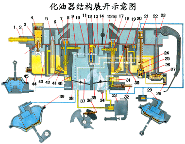
Carburetor deployment diagram

1. Carburettor body 2, inlet connection 3, inlet port filter 4, adjustable needle valve seat 5, sub-cavity transition foam tube 6, auxiliary cavity emulsification foam tube 7, and auxiliary cavity air correction hole 8 , Sub-cavity small-throat assembly 9, Sub-cavity small-throat nozzle 10, Sub-chamber small-throat 11, Acceleration pump-out needle valve 12, Acceleration pump nozzle 13, Main chamber small throat 14, Damper 15, Main Cavity throat nozzle 16, main cavity throat assembly 17, main cavity air compensation orifice 18, main cavity emulsion foam tube 19, main cavity main orifice 20, idle air volume orifice 21, enriched plunger 22, acceleration Pump push rod 23, accelerating pump lever 24, push rod 25, ball valve 26, thickened valve orifice 27, acceleration pump 28, accelerating pump ball valve 29, air-conditioning vacuum controller 30, main chamber idle volume hole 31, main cavity transition Spout 32, carbon monoxide adjustment screw 33, electromagnetic idle shutoff valve 34, rocker arm 35, main chamber throttle 36, idle adjustment screw 37, rocker arm 38, subchamber throttle 39, sub-cavity vacuum controller 40, subcavity transition nozzle 41. Sub-cavity main volume hole 42, sub-cavity transition volume hole 43, float 44, carburetor lower body 45, choke valve air-space controller 46, Oil needle
Corrugated Machine Belt,Waterproof And Oil Proof Bag Filter,Waterproof Bag Filter,Cement Industry Bag Filters
Industrial Dust Collector , Filter Bag Co., Ltd. , http://www.nbdustcollector.com
![<?echo $_SERVER['SERVER_NAME'];?>](/template/twentyseventeen/skin/images/header.jpg)